-
Test Service

-
Analysis Service

-
Accreditations/Approvals

- First time visitors
-

- Contact Contact
- JAPANESE


TEST SERVICE
FATIGUE TEST
Summary – Fatigue test types and methods
Contents
- What is Fatigue Testing?
- Types and methods of fatigue testing – JIS and ASTM standards
- Fatigue testing machines and principle
- What is S-N curve/S-N diagram? (Knowledge of fatigue testing)
- Fatigue test conditions
- Frequency for fatigue testing and its effect
- Fatigue testing of rubber and plastics
- Contracted fatigue testing
- Fatigue testing and endurance testing
What is Fatigue Testing?
Fatigue testing is a form of mechanical testing in which specimens taken from a material are subjected to cyclic loading by such means as compression, tension, ultrasonic wave, and heat. To determine the point at which the failure of material occurs (fatigue limit), multiple specimens are tested under different loads to record the number of cycles to failure of each specimen. The more the number of tests, the more likely you will understand the properties of the entire material.
Fatigue failure is a material failure that occurs as a result of excessive cyclic loading. Even a small load that does not affect a material causes the material to fail after cyclic loading. Invisible many different micro-cracks occur and grow, resulting in failure of the material. An example of fatigue fracture is that you can cut a wire with a small force by bending it repeatedly.
Fatigue is the most common form of breakage of machines and structures, accounting for up to 80% of all of their failures. Therefore, fatigue strength (a measure of the capability of a material to carry a load without failure) is a critical factor in designing machines and structures.
Fatigue strength can be estimated from literature and handbooks, but the fatigue strength of a material may differ depending on heat treatment or defect distribution on the material. The following will deepen your understanding of fatigue testing.
Material strength and mechanics in fatigue testing

=Question=
Suppose that member 1 (material A, diameter: 5 mm) breaks under a load of 1000 kg while member 2 (material B, diameter: 10 mm) breaks under a load of 1500 kg. Which material is stronger, A or B? Can we say that material B is stronger because the load is greater on member 2?
=Answer=
The answer is that material A is stronger. This is explained as follows:
When a diameter differs by a factor of 2, the cross-sectional area differs by a factor of 4. The cross-sectional area of member 2 is four times larger than that of member 1 but the load on member 2 is only 1.5 times greater. Therefore, we can see that load is not an appropriate indicator of the strength of a material.
As an objective index, load per unit cross-sectional area (P/A, where P is load and A is cross-sectional area) is used. This index is called stress, expressed by the Greek letter σ. The most common unit used for stress is MPa (=N/mm2).
In the question above, the strength of material A: σA=500 MPa, and the strength of material B: σB=187MPa—material A is approximately 2.7 times stronger than material B.
Types and methods of fatigue testing – JIS and ASTM standards
The following explains various types of fatigue tests and how they are conducted.
How to apply forces to test specimens are classified into the following three methods:
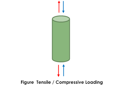
✓Axial(Tension, compression)
✓Bend(3-point bend, 4-point bend, plane bend, rotational bend)
✓Torsion (shear)
The basic method is axial force fatigue testing, in which a uniform, perpendicular force is applied to the entire cross section. In bending, stress applied on the specimen differs at each location on the cross section, that is, when a plate is bent, the stress is highest at the surface and zero at the center. Even if the same stress is applied, fatigue strength will be lower under axial loading than under bend loading. In shear, force is applied parallel to the cross section of interest. Shear stress occurs in fasters and joints, such as pins, bolts, spot welds, and rivets. In torsion, force is applied parallel to the surface, resulting in fatigue strength lower than the fatigue strength under axial and bend loading.
As above, there are a variety of fatigue test methods, each for a different objective of testing.
The representative test methods are the following. Click on the test name for details.
- – Rotating bending fatigue test
- – Tensile/compressive fatigue testing (High cycle fatigue testing)
- – Tensile/compressive fatigue testing (Low cycle fatigue testing)
- – Gigacycle fatigue testing
- – Plane bending fatigue testing
- – Thermal fatigue testing
- – Torsional fatigue testing
- – Ultrasonic fatigue testing
- – Internal pressure fatigue testing
- – Fatigue crack growth testing (Fatigue crack propagation testing)
The results of fatigue testing above are sometimes output as a curve called an S-N diagram, which plots the relationship between applied stress and the number of cycles to failure. Click here for details about the S-N diagram.
For conducting a fatigue test, you will need to start with considering which type of fatigue testing needs to be conducted among various types of fatigue testing as is mentioned above. It is desirable to use load conditions that are as close as possible to those the object to be tested will be subjected to. The contents of this topic may help you to decide which fatigue test is necessary for the object of interest. If you are not sure what test method is appropriate for your needs, please feel free to contact us. We are always ready to have discussion with you to suggest suitable test methods.
In the following sections, each type of fatigue test will be explained in detail.
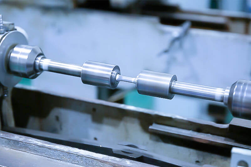
Rotating bending fatigue test
[Objective]
– Applicable to components that are subjected to radial loads, for example, a rotating shaft to which the self-weight of the equipment is applied.
– This testing is for metallic materials.
– In general, fatigue tests are conducted in the high cycle region below the proof stress, and the relationship between the stress and the number of cycles to rupture (S-N diagram) is plotted.
[Loading method]
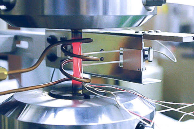
– Cyclic bending stress is applied to a round bar specimen by rotating it with bending moment applied to.
– Our laboratory uses Ono-type rotating bending fatigue testing machines among existing various types of machines.
– While loading is in a single direction, stress on the specimen is reversed when it is rotated halfway.
[Feature]
– Rotating bending fatigue testing is a simple test. However, it can be affected even by a slight eccentricity or misalignment of the specimen. Our laboratory sets permissible tolerance as close as within 0.02 mm on eccentricity and within 0.05 mm on specimen alignment.
– The testing machine is powered by a motor, capable of loading at a frequency of 3600 per minute. It takes only approximately two days to complete testing of 10 million cycles, which is defined as fatigue limit in general.
– This test is relatively inexpensive and takes a short period of time.
[Difference between plane bending fatigue testing and rotating bending fatigue testing]
– Both tests apply bending stress to the specimen repeatedly, but their test conditions are different.
– Even the stress conditions are the same, results obtained from plane-bending and rotating-ending fatigue testing may be different depending on factors affecting the fatigue life of the materials.
[Applicable standards (JIS and ASTM standards)]
– JIS Z 2274 Method of rotating bending fatigue testing of metals
– JIS Z 2286 Method for high temperature rotating bending fatigue testing of metallic materials
[Rotating bending fatigue test procedure]
– The test specimen is placed in the machine with one end fixed and the other end mounted to the fixture, and aligned within the specified tolerance.
– Required load is calculated using the beam bending theory. Weights corresponding the load are mounted to the testing machine to start the test.
[Test specimen for rotating bending fatigue test]
– The standard test specimen has a parallel section in the center of the specimen (JIS).
– The standard diameter of the test section is approximately 6 to 10 mm.
[Output]
– Table of test results (specimen code, specimen dimensions, stress, cycles to failure, and other information)
– Relationship between stress amplitude and number of cycles to failure
[Rotating bending fatigue testing machine]
– Ono-type rotating bending fatigue testing machine
Tensile/compressive fatigue testing (High cycle fatigue testing)
[Objective]
– Tensile/compressive fatigue testing is conducted to evaluate fatigue life or fatigue limit of components designed for use below the material’s proof stress.
– High-cycle fatigue testing is the most standard method for obtaining fatigue strength data of materials.
– Generally, fatigue tests are conducted in the high cycle region below the proof stress, and the relationship between stress and the number of cycles to failure (S-N diagram) is obtained.
[Loading method]
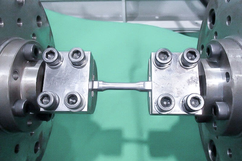
– Tensile/compressive load is repeatedly applied to the specimen in the axial direction. (Please see Figure Tensile/Compressive Loading.)
[Feature]
– Uniform stress is applied to the entire cross section of the specimen.
– Small to large specimens are be tested at our laboratory on testing machines with a wide range of load capacities.
– Full-size actual components can be tested with necessary fixtures manufactured at our facility.
[Applicable standards (JIS and ASTM standards)]
– JIS Z 2273 General rules for fatigue testing of metals
– ASTM E466 Standard Practice for Conducting Force Controlled Constant Amplitude Axial Fatigue Tests of Metallic Materials, and
-many other standards
[Tensile/compressive fatigue testing (high cycle fatigue testing) procedure]
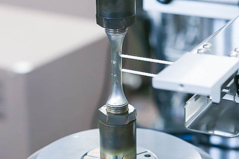
– Tensile/compressive fatigue testing is conducted using an electrohydraulic servo testing machine.
– The tests are typically performed under load-control.
– The specimen is clamped in a testing machine using hydraulic chucks and female threaded flanges. After one end of the specimen is fixed to the machine, the other end is fixed.
– Load is calculated from specified stress and the cross-sectional area of the specimen and inputted to the control panel to start the test.
[Test specimen for tensile/compressive fatigue testing (high cycle fatigue testing)]
– Round-bar or plate specimen having parallel section in its center
[Output]
– Table of fatigue test results (specimen code, specimen dimensions, stress amplitude, number of cycles to failure, and other required information)
– Relationship between stress amplitude and number of cycles to failure
– The relationship between peak load and cycles and that between peak displacement and cycles
[Tensile/compressive fatigue testing machine (high cycle fatigue testing machine)]
– Electrohydraulic servo fatigue testing machine
Tensile/compressive fatigue testing (Low cycle fatigue testing)
[Objective]
– The objective of this test is to evaluate the fatigue life of components that will be locally subjected to stress exceeding the material’s proof stress. Area around stress concentration area such as a step or circular hole of a component is likely to experience such stress and deform plastically.
– Low-cycle fatigue strength at high temperature is required for designing high-temperature components including turbine blades, piping, and pressure vessels.
– The relation between stress range and cycles to failure (ε – N) is obtained.
[Loading method]
– Tension or compression is repeatedly applied to the specimen in the axial direction. (Please see Figure Tensile/Compressive loading.)
[Feature]
– Small specimens are generally used. The fatigue life obtained from this testing is generally not more than 105 cycles.
– Energy for deformation is higher compared with high-cycle fatigue testing. Therefore, cyclic load is applied slowly to prevent heat generation.
[Applicable standards (JIS and ASTM standards)]
– JIS Z 2279 Method of high temperature low cycle fatigue testing for metallic materials
– ASTM E606 Standard Test Method for Strain-Controlled Fatigue Testing
[Tensile/compressive fatigue test procedure]
– An electrohydraulic servo testing machine is used.
– Testing is performed generally under strain-control using a triangle waveform.
– Controlled strain is in the axial or diameter direction.
– The specimen is clamped in a testing machine using hydraulic chucks and female threaded flanges. After one end of the specimen is fixed to the machine, the other end is fixed.
– The extensometer attached to the specimen controls the actuator.
– An electric furnace or induction heating is used for high-temperature testing.
[Test specimen for tensile/compressive fatigue testing (low-cycle fatigue testing)]
– Round-bar specimen having parallel section in the center
[Output]
– Table of fatigue test results (specimen code, specimen dimensions, strain range, number of cycles to failure, and other required information)
– Relationship between strain range (total strain, elastic strain, and non-elastic strain) and number of cycles to failure
– Relationship between peak load and cycles
– Hysteresis loop
[Tensile/compressive fatigue test machine (Low-cycle fatigue test machine)]
– Electrohydraulic servo fatigue test machine
Gigacycle fatigue testing
Gigacycle fatigue testing refers to a test in which low stress is applied to the specimen until it fails in the gigacycle (109 cycles) range. Generally, such testing takes a long period of time and is said to be difficult to perform. Ultrasonic fatigue testing, where a frequency of 20 kHz is achieved, makes gigacycle fatigue testing possible but thermal effects have to be considered because the specimen itself generates heat during testing.
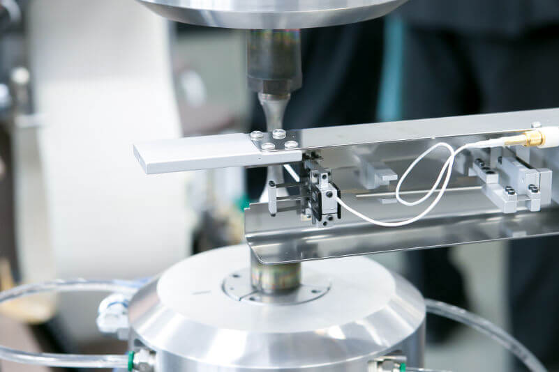
Plane bending fatigue testing
[Objective]
– Plane bending fatigue testing is performed for relatively thin plate components that are subjected to bending loads during their use, for example, steel plates for automobiles.
– It is applicable to not only steels but also nonferrous materials (aluminum, titanium, magnesium, copper, etc.) and plastics.
– In general, fatigue tests are conducted in the high-cycle region below the proof stress, and the relationship between stress and the number of cycles to failure (S-N diagram) is plotted.
[Loading method]
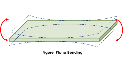
– Bending moment is repeatedly applied to a plate specimen.
– It might be helpful for you to imagine grasping the ends of a thin plastic sheet with both hands and repeatedly bending it back and forth. (See Figure Plane Bending.)
[Feature]
– Material surfaces can be left intact on the specimen, which enables to study effects of surface treatment and roughness on the fatigue strength.
– Such specimens that contain weld beads can also be tested.
– The required specimen size is relatively small, enabling sampling from small parts.
– Large specimens can also be tested using an electrohydraulic servo bending torsional fatigue testing machine.
[Difference between plane bending fatigue test and rotating bending fatigue test]
– Both tests apply bending stress to the specimen repeatedly, but their test conditions are different.
– Even the stress conditions are the same, results obtained from plane-bending and rotating-ending fatigue testing may be different depending on factors affecting the fatigue life of the materials.
[Applicable standards (JIS and ASTM standards)]
– JIS Z 2275 Method of plane bending fatigue testing of metal plates
[Plane bending fatigue test procedure]
– For setting the specimen, both ends of the specimen are fixed, and the bending angle is adjusted while the bending moment or strain generated by the specimen is monitored.
– To set stress, one of the following two methods is used: moment method for general use, and strain-gage method for thin specimens and high-temperature testing.
✓Moment method
Stress σ is calculated from cross-section coefficient Z calculated from the specimen configuration based on the bending beam theory and bending moment M.
✓Strain gauge method
Stress σ is calculated by output from the strain-gage attached at the center of the specimen multiplied by Young’s modulus E. Young’s modulus at the test temperature needs to be known priory.
[Plane bending fatigue test specimen]
– The standard specimen has a reduced section in the center.
– Standard plate thickness is 1 mm to 7 mm. For plates thinner or thicker than this, please contact us.
– Samples other than plates may also be tested.
[Output]
– Table of test results (specimen code, specimen dimensions, moment, stress, cycles to failure, and other information)
– Relationship between stress amplitude and number of cycles to failure
・繰返しに伴うモーメントの変化
– Relationship between strain and cycles (only when using a strain gage)
[Plane bending fatigue testing machine]
– Electrohydraulic servo bending torsional fatigue testing machine
– Mechanical bending torsion fatigue testing machine
Thermal fatigue testing
[Objective]
– Change in temperature causes components to expand or contract. When a component is constrained in some way, it cannot expand and contract freely and stress is generated. This stress is called thermal stress.
– Cyclical temperature change of some hundred degrees C causes fluctuation of thermal stress in the material and results in fatigue fracture, called thermal fatigue.
– Thermal fatigue testing is applied to components subjected to temperature change during use or when they start or stop, for example, engine components, piping for high-temperature fluid or gas, and turbine blades.
– In thermal fatigue testing, the relationship between temperature change and the number of cycles to failure is evaluated.
– In thermomechanical fatigue testing, mechanical strain is periodically changed in addition to temperature to evaluate the specimen life to failure.
[Loading method]
– In thermal fatigue testing, the specimen is heated/cooled with the ends fixed to constrain the displacement.
– In thermomechanical fatigue testing, the specimen is loaded in tension/compression at a constant speed with both ends clamped while temperature varies.
[Feature]
– An electrohydraulic servo fatigue testing machines (capacity: 100 kN) is used.
– Testing is performed under strain control. Temperature is controlled while keeping the heating/ cooling rate constant by induction heating or forced cooling.
– In thermomechanical fatigue testing, changes in temperature and strain are synchronized. In-phase loading and out-of-phase loading are both available.
– Temperature: 900℃ maximum and 100℃ minimum; Heating rate: 2.0 – 5.0℃/sec. ; Cooling rate: 0.5 – 1.0℃ /sec.
(*Heating/cooling rate depends on the material and test temperature range. Trial testing will be conducted to establish test conditions.)
– Frequency is low compared with that for high-cycle or low-cycle fatigue, sometimes resulting in long test duration.
[Applicable standards (JIS and ASTM standards)]
– ASTM E2368 Standard Practice for Strain Controlled Thermomechanical Fatigue Testing
– JIS Z 2278 Method of thermal fatigue testing for metallic materials
[Thermomechanical fatigue test procedure]
– An electro-hydraulic servo fatigue testing machine is used.
– The tests are typically performed using a triangle waveform under strain-control.
– After one end of the specimen is fixed to the machine, the other end is fixed. Hydraulic chucks, female flanges are used for fixing the specimen.
– Output from the extensometer attached to the specimen controls the actuator.
– Induction heating is used for heating.
[Test specimen for thermomechanical testing]
– Round bar specimen
[Output]
– Table of fatigue test results (specimen code, specimen dimensions, strain range, number of cycles to failure, and other required information)
– Relationship between strain range (total strain, elastic strain, and non-elastic strain) and number of cycles to failure
– Relationship between peak load and cycles
– Hysteresis loop
[Thermomechanical fatigue test machine]
– Electrohydraulic servo fatigue test machine
Torsional fatigue testing
[Objective]
– Applicable to components subjected to cyclic torsional loads, for example, an engine, turbine, motor and shaft that transmits rotational torque.
– In general, testing is conducted in a high-cycle region below the proof stress to plot the relationship between stress and cycles to failure (S-N diagram).
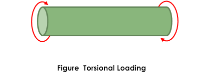
[Loading method]
– Torque (a pair of forces in the circumferential direction) is repeatedly applied to the test specimen, like squeezing a cloth.
[Feature]
– Torsional loading produce shear stress on the specimen.
– Actual component can be tested with necessary fixtures manufactured.
– For testing a small specimen, using a mechanical fatigue testing machine is recommended rather than an electrohydraulic servo bend and torsion fatigue testing machine, in consideration of test duration and cost.
– For testing a large or long specimen, using an electrohydraulic servo bend and torsion fatigue testing machine is recommended. The machine gives large space and allows a variety of load control methods.
[Applicable standards (JIS and ASTM standards)]
– None
[Torsional fatigue test procedure]
– To set the specimen, both ends of the specimen are fixed and the torsion angle is adjusted manually while torque generated by the specimen is monitored.
– After an end of the specimen is fixed to the testing machine, the other end is fixed. Torque calculated using the elastic theory is inputted to the control panel to start testing.
– An electric furnace or constant temperature chamber is used.
[Torsional fatigue test specimen]
– The standard specimen has a parallel section in its center.
– Each of the specimen grips are cut to make a flat surface.
[Output]
– Table of fatigue test results (specimen code, specimen dimensions, shear stress amplitude, number of cycles to failure, and other required information)
– Relationship between shear stress amplitude and number of cycles to failure
[Torsional fatigue testing machine]
– Electrohydraulic servo bend and torsion fatigue testing machine
– Mechanical bend and torsion fatigue testing machine
Ultrasonic fatigue testing
Ultrasonic fatigue testing is a test method in which a specimen is exposed to ultrasonic vibrations. Although a common electrohydraulic servo fatigue testing machine can only achieve a frequency of approximately 30 Hz, an ultrasonic fatigue testing machine can operate at a frequency of 20 kHz, thus accomplish a high-cycle fatigue test of 107 cycles. As the specimen produces heat during ultrasonic fatigue testing, continuous cooling during testing is necessary.
Internal pressure fatigue testing
Internal pressure fatigue testing is used to evaluate the fatigue endurance of pressure vessels. Pressure medium such as oil, water, or nitrogen gas, is sealed in the sample and boosted by using a hydraulic jack mounted on the electrohydraulic servo fatigue testing machine.
Fatigue crack growth testing (Fatigue crack propagation testing)

[Objective]
– This test determines the crack growth rate on a component in which cracks are allowed to exist or occur.
– Materials’ crack growth rate needs to be known for periodical maintenance and component replacement in plants.
– Crack growth rate is evaluated based on the stress intensity factor range ΔK, a fracture mechanics parameter.
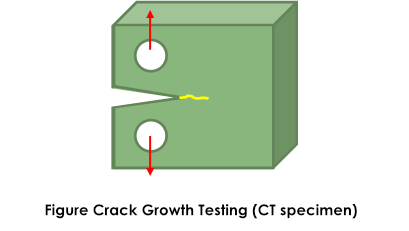
[Loading method]
– A specimen with a crack starter notch is repeatedly subjected to cyclic tensile or bending stress.
Figure Crack growth testing (CT specimen)
[Feature]
– Testing is conducted using a specimen and loading conditions that conform to the standards.
– The range of stable crack extension (Paris’s law) or the limit below which a crack will not grow (fatigue crack growth threshold ΔKth) is determined.
– Testing is available even in a high-temperature or high-humidity environment.
[Applicable standards (JIS and ASTM standards)]
– ASTM E647 Standard Test Method for Measurement of Fatigue Crack Growth Rates
– ISO 12108 Metallic materials — Fatigue testing — Fatigue crack growth method
[Fatigue crack growth testing (fatigue crack propagation testing) procedure]
– An electrohydraulic servo fatigue testing machine is used.
– Testing is conducted under load control.
– An appropriate loading method is used depending on the specimen configuration.
– Crack length is measured by the visual method or the compliance method that employs crack-mouth-opening displacement.
– Measured data is analyzed by our original analysis software in accordance with ASTM.
[Crack growth (crack propagation) test specimen]
– CT specimen
– CCT specimen
– Three-point bending specimen
[Output]
– Crack growth test data (specimen code, test force, range of stress intensity factor, cycles, crack length, crack growth rate, and other information)
– Relationship between crack length and cycles
– Relationship between crack growth rate and stress intensity factor range
– Results from Paris’ law fitting
[Fatigue crack growth testing machine (Fatigue crack propagation testing machine)]
– Electrohydraulic servo fatigue testing machine
Fatigue testing machines and principle
There are different types of fatigue tests and, for each test type, a specific type of fatigue testing machine is used. In the following, fatigue testing machines and their principle are simply explained.
As an introduction, fatigue testing machines uses mainly the following two control modes to apply cyclic load.
✓ Load control (stress control)
✓ Displacement control (strain control)
Generally, high-cycle fatigue tests are performed under load control and low-cycle fatigue tests under strain control.
Hereafter, each fatigue testing machine is explained.
Rotating bending fatigue testing machine
[Principle of rotating bending fatigue testing machine]
– Ono-type rotating bending fatigue testing machines perform four-point bending fatigue testing, where the specimen is supported at two points and loaded at two points.
– The bending moment between the two loading points is uniform, which is pure bending state with zero shear-stress.
– The machine is powered by a motor.
– Load is applied by weights, which keep constant stress on the specimen from the initial stage of testing to specimen failure.
[Machine specifications]
– Maximum moment capacity: ± 196 Nm
– Maximum cyclic rate: 60 Hz
– Maximum stress: Approximately 1100 MPa
[Test environment]
– Test atmosphere: In air; Corrosive-solution dropping (at room temperature)
– Temperature: Room temperature; 100℃ to 850℃
[Number of machines]
– 21 machines
– Capacity of ± 98 Nm: 20
– Capacity of 196 Nm: 1
[Related testing]
– Rotating bending fatigue testing
Tensile/compressive fatigue testing machine (High cycle fatigue testing machine)
[Principle of tensile/compressive fatigue testing machine (high cycle fatigue testing machine)]
– This machine is a closed-loop-hydraulic-servo-type fatigue testing machine consisting of a main frame (including an actuator), hydraulic power source, and controller.
– The controller is connected to a servo valve that controls hydraulic pressure to electric signals received.
– With the servo valve controlling load, strain, and displacement so that difference between set values and feedback values becomes zero, cyclic load is applied to the specimen set to the main body of the testing machine.
[Machine specifications]
– Capacity: 20 kN to 10000 kN
– Speed: Approximately 50 Hz maximum
[Number of machines available]
– 70 hydraulic servo machines
Tensile/compressive fatigue testing machine (Low-cycle fatigue testing machine)
[Principle of tensile/compressive fatigue testing machine (low-cycle fatigue testing machine)]
(The same principle as for the machines used for high cycle fatigue testing.)
[Machine specifications]
– Capacity: 20 kN to 100 kN
– Speed: Approximately 1 Hz maximum (under strain-control)
[Number of machines available]
21 machines
Gigacycle fatigue testing machine
Gigacycle fatigue testing refers to fatigue testing in which the specimen fails at cycles more than 9th power of 10. Using a common electrohydraulic servo machine for such testing is not practical because more than one year will be necessary even for testing at 30 Hz. Thus gigacycle fatigue tests are generally performed on an ultrasonic fatigue testing machine, which generates ultrasonic vibrations. The ultrasonic fatigue testing machine produces vibrations at 20 kHz, reaching gigacycles in the order of 10 to the 9th power.
Plane bending fatigue testing machine
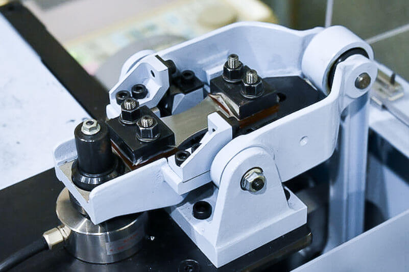
[Principle of plane bending fatigue testing machine]
– The machine applies bending moment mechanically to the specimen by using a crank to convert the rotary motion of the eccentric cam connected to the shaft to circular motion—the mechanism called Schenk type.
– A motor is used as the power source.
– Bending moment acting on the specimen is measured by using a torque cell (or load cell).
– The machine is also used for torsional fatigue testing using a round-bar specimen.
[Machine specifications]
– Maximum moment capacity: ± 15 Nm, ± 49 Nm, ± 80 Nm
– Maximum frequency: 33 Hz
– Maximum bending angle: ± 30°
– Control method: Angle control
[Test environment]
– Test atmosphere: In air only
– Temperature: -50℃ to 900℃
[Number of machines]
– 11 machines, including self-developed 6 machines
[Related testing]
– Plane bending fatigue testing
– Torsional fatigue testing
Thermal fatigue testing machine
[Machine specifications]
– Capacity: 100 kN
– Speed: 6 to 12 min/cycles
[Number of machines available]
6 machines
Torsional fatigue testing machine
[Principle of torsional fatigue testing machine]
– Oil flow into the rotary actuator is electronically controlled with high precision by the servo valve. The motion of the rotary actuator is feed-backed and controlled so that control signals correspond to the output.
[Machine specifications]
– Maximum torque capacity: ± 5000 Nm
– Maximum torsional angle: ± 50°
– Maximum frequency: 20 Hz (depending on the torsional angle for the specimen to be tested)
– Control method: Torque control, angle control (both digital)
– Maximum specimen length: 1.5 m
[Test environment]
– Test atmosphere: In air
– Temperature: -60℃ to 150℃
[Number of machines]
– 3 machines
Ultrasonic fatigue testing machine
An ultrasonic fatigue testing machine is a testing machine that vibrates the test specimen using ultrasonic waves. The object being tested can be exposed to vibration at 20 kHz, where the gigacycle (10 to the 9th power) regime will be reached in approximately two weeks.。
Internal pressure fatigue testing machine
An internal pressure fatigue testing machine is an electrohydraulic servo fatigue testing machine with a hydraulic jack attached to. Boosted pressure medium (e.g. oil, water, or nitrogen gas) is flowed into the test object to evaluate its fatigue endurance.
Fatigue crack growth testing machine (Fatigue crack propagation testing machine)
[Principle of machine]
– See [Principle of tensile/compressive fatigue testing machine (high cycle fatigue testing machine)].
[Machine specifications]
– Capacity: 100 kN; Frequency: 30 Hz maximum
[Number of machines available]
– 12 machines
Electrohydraulic servo fatigue testing machine
[Principle of electrohydraulic servo fatigue testing machine]
– The actuator is driven by hydraulic power to apply load to the specimen.
– The servo valve electronically controls oil flowed into the actuator. The motion of the actuator is controlled with feed-backed measured signals so that the control signals correspond to the output.
[Machine specifications]
– Maximum load capacity: ± 5 kN to ± 10000 kN
– Maximum displacement: ± 50 mm
– Maximum frequency: 50 Hz (depending on displacement of the specimen to be tested)
– Control method: Load control, displacement control, strain (extensometer) control
– Waveform: Sine wave, triangle wave, asymmetric triangle wave, random wave, etc.
– Maximum specimen length: approximately 3 m
What is S-N curve/S-N diagram? (Knowledge of fatigue testing)

An S-N curve (diagram), also referred to as a ⊿ε-N diagram, is a plot of the magnitude of load versus the number of cycles. In a fatigue test, the life of a specimen varies depending on the magnitude of the load (stress or strain). In an S-N diagram, the load (stress amplitude or strain range) is given on the vertical axis and the number of cycles to failure on the horizontal axis. The S-N diagram is separated into two regions at around 10⁴ cycles to 10⁵ cycles-low-cycle fatigue (fatigue life is short) and high-cycle fatigue (fatigue life is long). Significant difference between the low-cycle fatigue and high-cycle fatigue is the presence of macroscopic plastic deformation. High-cycle fatigue is primarily elastic because stress is smaller than the material yield strength; low-cycle fatigue is accompanied with plastic deformation of the entire material with stress larger than the yield strength.
High-cycle fatigue
Many machines and structures are designed and used in the elastic stress range. As evaluation is based on stress, fatigue testing is conducted under load (stress) control. Displacement control is not suitable for high cycle fatigue due to small deformation although some testing is performed under displacement control. Since deformation is small, heat generation during loading is also small, enabling testing at a relatively high speed.
Low-cycle fatigue
Even if the majority of a part is elastically deformed, areas around the stress concentration area, such as a step or circular hole, can be plastically deformed due to factors other than external forces (e.g. vibration, temperature fluctuation, wall thinning due to wear or corrosion). Since the surrounding area remains elastically deformed, deformation in the stress concentration area is constrained by the surrounding area. In order to simulate failure in such area, strain control is used in low-cycle fatigue testing. Due to significant deformation, the testing speed needs be low enough to avoid heating.
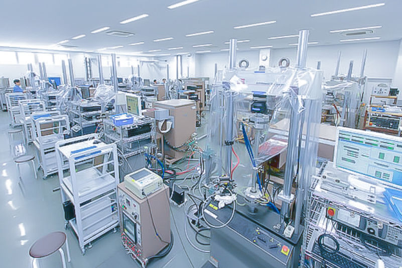
Fatigue test conditions

Kobe Material Testing Laboratory, Ltd. offers fatigue tests under various conditions. For example, our electrohydraulic servo fatigue testing machines are available with a wide range of capacities from 5 kN to 10000 kN, making it possible to test huge and small objects. Test temperature of -196℃ to 1400℃ is available by using liquid nitrogen or electric furnaces. Other available tests include torsional fatigue testing, rotating bending fatigue testing, plane bending fatigue testing, miniature fatigue testing, and fatigue testing of actual components. If you have trouble determining fatigue test conditions, our experts are here to discuss test conditions suitable to your needs. KMTL is a Japan’s leading independent laboratory that is not capitalized by any major corporation and is the first laboratory in Japan to obtain Nadcap accreditation for material testing. We are highly regarded for the neutrality and the reliability of our data.
Frequency for fatigue testing and its effect
Frequency available for each fatigue test depends on stress and displacement. Low frequency needs to be used for fatigue testing involving large force and deformation; high frequency can be used for fatigue testing with small force and deformation. Recently, fatigue testing at extremely high frequency of 20 kHz—ultrasonic fatigue testing—is available. Although ultrasonic fatigue testing makes fatigue testing in the gigacycle regime available, data need to be interpreted with thermal effects due to heat generation in the material taken into consideration.
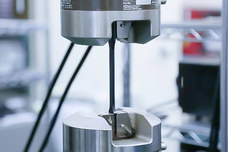
Fatigue testing of rubber and plastics

Fatigue fracture occurs also in rubber and plastics. Unlike steels, where the S-N curve remains almost flat after 106 to 107cycles, rubber and plastics do not have definite fatigue limits and their stress to rupture decreases as the number of cycles increases. We have a lot of experience in fatigue testing of rubber and plastics. Not only fatigue testing at room temperature, low temperature, and high temperature, but also testing in constant temperature and humidity environment is available at our laboratory.
Contracted fatigue testing

Kobe Material Testing Laboratory, Ltd. accepts contracted fatigue testing. Total support is available from planning of appropriate fatigue test methods to testing and reporting. As a leading independent laboratory that is not capitalized by any major corporation and the first laboratory in Japan to obtain Nadcap accreditation for material testing being, we are highly regarded for the neutrality and the reliability of our data.
Fatigue testing and endurance testing

One of the most often asked question is what the difference between fatigue testing and endurance testing is. The difference is summarized below.
Endurance testing is conducted to evaluate the durability of specific items such as actual components and structures. To be specific, the item will be repeatedly subjected to stress that would be actually applied to the item in order to evaluate how long it lasts.
Fatigue testing applies excessive load to an object to study from where and through what process the object will fail. Not only the data obtained from the test, but also observing the fracture surface is important.
✓ When and where are cracks originated and how they grew?
✓ Whether the failure started from a defect or inclusion in the material or not?
✓ If an actual part was tested, did it break from the expected location?
As above, fatigue testing gives different data from different viewpoints. Although endurance testing and fatigue testing is sometimes considered to be similar, it is necessary to understand that they are used in different situations.
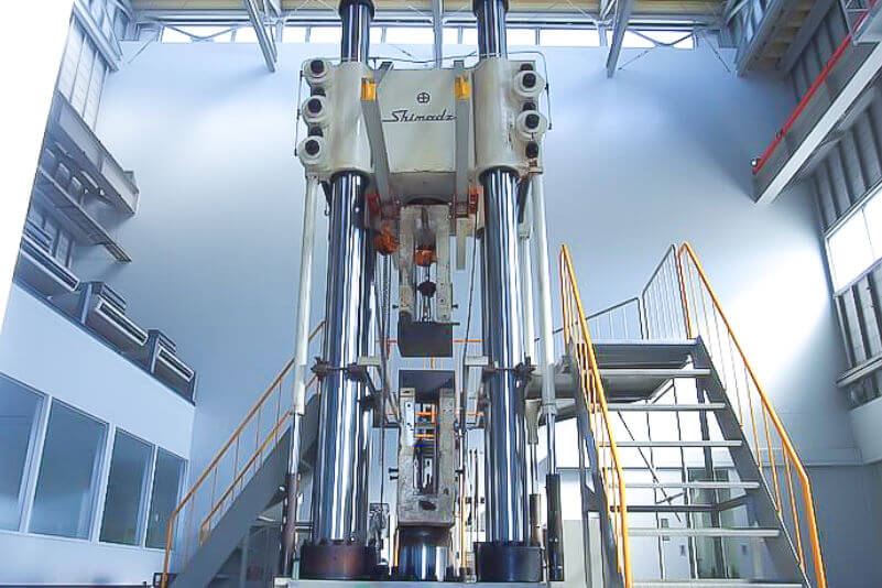
Our FATIGUE TEST
Fatigue testing at KMTL
For fatigue-resistant design for components and structures of aircraft, ships, automobiles, and power plants, understanding their fatigue characteristics is necessary. In addition to standard fatigue tests such as rotation bending and tensile/compressive, we conduct a wide range of fatigue testing: creation of fatigue design curves from low-/high-cycle fatigue tests, fatigue crack propagation property determination, corrosion fatigue testing under certain environmental conditions, thermal fatigue testing, large scale fatigue testing simulating actual working stress condition, and more.

High-temperature low-cycle fatigue testing
Main equipment
| Capacity | 800kN, 500kN, 250kN 200kN, 100kN, 50kN 30kN, 25kN, 20kN *Underlined: MTS machines |
|---|---|
| Test temperature | -196℃ to 1200℃ |
| Capacity | 3k Nm 5k Nm |
|---|---|
| Test temperature | RT |
| Capacity | 100 to 200 Nm (100 Nm) (200 Nm) |
|---|---|
| Test temperature | RT to 850℃ |
| Capacity | 10 to 80Nm (10 Nm) (15 Nm) (50 Nm) (80 Nm) |
|---|---|
| Test temperature | RT to 700℃ |
Applicable standard
| JIS B 1081 |
| JIS Z 2273 |
| ISO 3800 |
| ASTM E466 |
| JIS Z 2274 |
| JIS Z 2279 |
| ASTM E606 |
FAQ
FAQ
-
Q. What is fatigue testing?
- A. Fatigue testing is a test in which a specimen taken from a material is repeatedly loaded by different methods (compression, tension, heat, ultrasonic wave, etc.). Multiple specimens are tested with different load magnitudes to obtain the cycles to failure. Then the limit at which failure of the material occurs (fatigue limit) is determined.
-
Q. What types and JIS standards are available for fatigue testing?
- A. How to apply force to the specimen can be classified into the following three methods: axial (tensile/compression), bend (three-point, four-point, plane, and rotation bending), and shear torsional loading. Axial loading is the most common loading method. For information on JIS standards, please refer to “Types and methods of fatigue testing “JIS and ASTM standards“.
-
Q. What is plane bending fatigue testing?
- A. Plane bending fatigue testing is performed for relatively thin plate materials that are subject to bending loads during their use, for example, steel plates for automobiles. In general, fatigue tests are conducted in the high-cycle region below the proof stress, and the relationship between stress and the number of cycles to failure(S-N diagram)is plotted.
-
Q. What is thermal fatigue testing?
- A.In engine components, gas piping, and turbine blades, temperature variation due to environmental temperature change causes internal thermal stress change, causing thermal fatigue. In thermomechanical fatigue testing, mechanical strain is also periodically changed to evaluate the life of the specimen to failure.
-
Q. What is torsional fatigue testing?
- A. Torsional fatigue testing is a test method that is applicable to components subjected to cyclic torsional loads, e.g. engines, turbines, motors, and shafts that transmit rotational torque. Generally, testing is conducted in a high-cycle region below the proof stress, and the relationship between stress and cycles to failure(S-N diagram)is plotted.
-
Q. What is S-N curve or S-N diagram?
- A. An S-N curve (diagram) is a plot of the magnitude of load versus the number of cycles. In a fatigue test, the life of a specimen varies depending on the magnitude of the load (stress or strain). In an S-N diagram, the load (stress amplitude or strain range) is given on the vertical axis and the number of cycles to failure on the horizontal axis. For more information, please refer to “What is S-N curve/S-N diagram? (Knowledge of fatigue testing).“
-
Q. Does Kobe Material Testing Laboratory undertake subcontracted fatigue testing?
- A. Fatigue tests under various conditions are available at Kobe Material Testing Laboratory. For example, fatigue tests are available from very small to very large objects with our electrohydraulic servo testing machines with a capacity of 5 kN to 10000 kN. Other fatigue tests available include torsional, rotation bending, plane bending fatigue, and miniature fatigue tests, and fatigue testing using an actual component.
TEST SERVICE
Test Service
KMTL provides a wide range of testing services including fatigue and creep testing to support safety and security for society at large.